5. The software and hardware of the XO. Interaction with the physical world.
Software
The XO1 ("green ceibalita" N.T: nickname for the XO in Uruguay), given to each child and teacher in public schools around the country when Plan Ceibal was implemented, has the Linux operating system installed with a lightweight Fedora distribution and a graphical user interface (GUI from the English initials) called SUGAR; This interface was specially designed for children to explore, discover and be able to create working collaboratively: "This interface is based on three very simple principles about what makes us human: (1) everyone is a teacher and a student, (2) human beings are social beings by nature, and (3) human beings are expressive by nature.".
Sugar Labs's Sugar
Sugar was written in the (interpreted) programming language Python (1990-2012) and is Free Software; the culture of Free Software is a powerful learning culture; it is about a concept radically different to the proprietary software that is so extended in our society; a culture that encourages a critical spirit, the liberty to act, and the critique of ideas. Probably the development and impact the OLPC Project is owed to having been embraced from the beginning by the global free software community composed by a huge number of collaborators and creators in permanent communication.
As can be read in the Sugar Wikipedia article: "Sugar is developed based on the playground metaphor. Focused on boys and girls aged 6 to 12, Sugar is a GUI thought for sharing activities in a network with other children in school. Each activity may be shared in the internal network that is represented as a view of the school playground. The 4 views of Sugar: neighborhood, friends group, home, and Journal, represent in the first place the spatial environment where the child is developing going progressively towards himself and the activities available in his computer until reaching a personal journal of all activities and works done by the student and his group of friends".
Sugar is inspired in the work of Dr. Alan Kay of the Xerox PARC with the development of a personal computer for children called "Dynabook".
The work of Dr. Alan Kay may be the first to make reference to the concept of a "children's machine", the Dynabook, a tablet that has its first version in the XO1. We suggest reading the article "A Personal Computer For Children Of All Ages" by Alan C. Kay, Xerox Palo Alto Research Center, (Originally published in the Proceedings of the ACM National Conference, Boston Aug. 1972), transcribed in Kay (1972).
For a detailed description of the origins of Sugar and its development, read Bender (28/12/2011).
Hardware. Interaction with the physical world.
A computer may interact with the physical world through devices known as peripherals. These may be classified in:
- input/output peripherals (such as USB ports),
- output peripherals (such as the display, or the embedded speakers), as well as
- input peripherals (such as the keyboard, the Mouse, the camera and the embedded microphone)
The XO netbooks interact with their environment through the embedded input and output devices and through it's 3 USB 2.0 ports.
In the case of the XO1 (CL1A) the input devices are:
- The keyboard
- The touchpad (with left and right buttons)
- The gamepad with four direction buttons
- The screen rotation button
- The four game buttons (circle, square, ok and x)
- The on/off button
- The embedded camera
- The embedded microphone and the external microphone jack
- Embedded magnetic sensors included to detect whether the XO is closed (in which case it can suspend or shutdown) or if the screen is rotated to enable the ebook mode (in which case it remains on).
And the output devices are:
- The display
- Embedded speakers and line out
Source: OLPC XO1
Exclusive features of the XO peripherals
The embedded camera
In the design process of the netbooks of project OLPC it was decided to use a different kind of hardware and control software in order to expand its features.
According to the hardware specifications of the OLPC XO, it embeds a fixed-lens video camera to the right of the screen, 640x480 resolution, and a maximum frequency of 30 fps (frames per second), Omnivision OV7670. The control parameters for the same may be adjusted in software to allow its use as a photometric sensor for educational applications. Although this functionality was planned, currently it can be used as a photometric sensor only qualitatively.
A green led positioned above the camera is lit when it is active.
The screen
The screen works in two high resolution modes: a mode of high transmissive color, and a high resolution reflective mode to allow it to be readable under sunlight. This latter was thought so that children may use their netbooks outdoors in the daytime (for instance in the recess playground at their school or in a park). In the design of the XO1.75, a light sensor has been included to make the automatic adjustment according to the existing light level (OLPC News XO1.75).
The sound board. Technical specifications of the XO board.
One embedded component in the hardware of any computer is the sound board (or card) which is often integrated to the main board (motherboard). It is a set of electronic components dedicated (basically) to the processing of audio signals. In order to work properly, a device driver needs to be installed, a software component specifically designed for it.
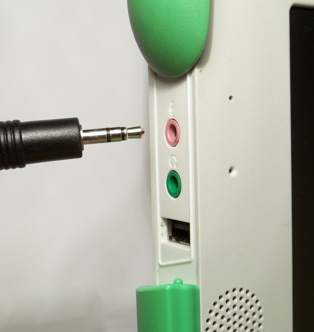
The signals that are exchanged with the board are electric oscillations that and may be classified as input signals and output signals. These signals enter or leave the board by hooking input devices (microphone) or output devices (headphones or amplified speakers) to it: this connection is done by means of a male audio connector (plug) attached to the connecting device and the embedded female audio connectors (socket). Currently the female connectors in the board may be identified by means of a color code: for example the external microphone socket is colored pink while the line out socket is colored green.
The XO uses standard cylindrical TS audio connectors of two contacts (mono) or TRS three contacts (stereo) of 3.5mm diameter (like the one in the picture next to the external microphone socket of the XO1). The sound board of the XO offers input as well as output internally and externally.
The embedded speakers
Two speakers have been included (with stereo sound) located to the sides of the display. The same respond to a range of frequencies between 480 Hz and 40kHz. The internal amplifier can provide 1.4 W continuously to each of them.
External socket for headphones or speakers (line out)
By connecting headphones or external speakers to this socket, the internal speakers are disabled. The internal amplifier can provide 30 mW to the headphones continuously with a 32 ohm impedance.
The embedded microphone
An electret microphone (mono) located to the left of the display is included. A green led located above it lights up when it is active.
External socket for microphone, switch and sensors
In the design of the hardware for the netbooks of the OLPC project, it was decided to use a different kind of microphone jack socket in order to expand its features and to be able to use it as a data acquisition interface by means of connecting it to sensors. It is possible to connect an external electret microphone, a switch, or another sensor.
XO1 (CL1A): the audio subsystem is based on the '97 standard audio codec. The external microphone input is monoaural (mono) and it includes a programmable gain preamplifier. A DC blocking capacitor may be connected in software in order to measure audio signals or AC. To utilize this input as a sensor the capacitor needs to be disconnected. A polarizing 2v input voltage, that is controlled by software, may be applied. This is used if it is desired to feed an external electret microphone or if it is desired to sense if an external switch is open or closed.
The Analog Devices AD1888 audio chip (Analog Devices (2003)) has the capability of measuring continuous current voltages. The configuration for the external microphone for sensor mode is done through the audio control program called Alsamixer; an electronic switch may be controlled by means of the "Analog Input" option. The high pass filter may be enabled/disabled by means of the "High Pass Filter" option. The polarizing voltage may be applied by using the "V_REFOUT" option.
XO1.5 (CL1B): The audio subsystem is based on the HD standard Audio codec. The external microphone input is stereo and includes a programmable gain preamplifier. It is possible to connect a blocking DC capacitor to this input in order to measure audio signals or AC. In order to use this input in sensor mode, the capacitor needs to be disconnected. A polarizing voltage of 1.5V or 2.5V may be applied to this input and controlled from software.
XO1.75 (CL2): The audio subsystem is based on the I2S Audio codec (OLPC XO1.75). The external microphone input is stereo and includes a programmable gain preamplifier. It is possible to connect a blocking DC capacitor from software in order to measure audio signals or AC. To be able to use this input in sensor mode, the capacitor needs to be disconnected. A polarizing voltage of 2V or 2.5V may be applied to this input and controlled from software.
Mic sensors for the XO
The XO netbook of the OLPC project that has been distributed in Uruguay through the Plan Ceibal organization in any of its models XO1, XO1.5, XO1.5 lite, as well as XO1.75 (that includes a light sensor and 3 axis accelerometer), and the XO3 prototype (OLPC XO3) admit the reading of AC voltage, DC voltage and resistance sensors connected to the external microphone jack. The reading of the same can be done from some included Activities from the SUGAR graphical user interface (GUI) such as Measure, TurtleBlocks and Scratch. The present work focuses on the use of sensors by using the first two mentioned activities.
According to the hardware characteristics of the XO1, one sensor at a time may be connected (to the external mono input) while the XO1.5 and XO1.75 (external stereo input) are capable of connecting two sensors at the same time, multiplying the possible applications that can be designed with them.
The potential of these sensors lies in the simplicity of their construction and low cost, as well as the real possibility of writing diverse programs that interact with the information read and offer the widest range of responses imaginable. Since there is no limit to creativity, they can be applied to a huge range of objectives.
By connecting to the external microphone jack, it is possible to read AC, DC voltages, resistance, but this measuring capability can be extended if transducers are available: electronic devices that produce voltages or resistance in proportion to a physical magnitude that one wishes to measure. Based on them, sensors can be constructed. Some examples:
- Temperature sensor (for example the LM35): a component that produces voltage in proportion to the temperature it is at
- Hall sensor (for example the A1302): a component that produces voltage in proportion to the magnetic field intensity it is at
- Potentiometer: a component whose resistance depends on the angle to a reference position (such as we find for controlling volume and pitch in sound systems)
- LDR: a component whose resistance depends on the lighting level it receives
- Thermistor: a component whose resistance depends on its temperature
By integrating these capabilities and allowing the use of sensor, we are using the XO (along with the software and programs we create) as a device known as DA interface for data acquisition turning it into a powerful measuring instrument for use in Physics, Chemistry and Biology labs. Although these devices have existed in physics laboratories of secondary schools in our country for decades, it is beginning with Plan Ceibal that we have the opportunity to let each student have one.
Translating the physical measurements into data that a computer can interpret and process
Analog to Digital Conversion
When a sound reaches the sensitive membrane of a microphone, it produces mechanical oscillations. The microphone turns these vibrations into electric oscillations, which consist in a set of voltage values that vary continuously in time usually known as analog signal. It consists of alternating voltages (AC for Alternating Current).
If it is desired for a computer to process the analog signal obtained from a microphone, the signal needs to be translated to a format the computer can process, known as digital signal. It consist of a discrete set of integer values that are obtained from the original analog signal. This translation is necessary because the computer can only process digital signals.
The electronic circuit that performs this translation is known as analog to digital converter (ADC from its initials).
Digital to Analog conversion
Opposite to the formerly described process, a digital audio signal comes from a digital file (for example, an *.mp3) and to be able to be transformed into sound, it first needs to be transformed into an analog signal by means of a circuit called digital to analog converter (DAC for its initials) that performs the opposite function from a ADC. It is this analog audio signal the one that feeds the line out of the sound board in order to produce sound in our headphones or amplified speakers.
Both the ADC and the DAC can be found (for example) in the sound board computer.